Web Guides Used For Edge Position Control
Corps

A variably baggy or cambered web will cause the web to track toward the variably tighter side. Variabilities in roller traction or drag can cause a steering of the web. Changes in tension will cause changes in how straight the web travels downstream. At zero tension, edge position control is essentially lost. However, there are other edge movement factors which include nip roller draw variations, aerodynamics and so on. Web guides are used to bring the edge or center of a web to a specific CD position. The guide location may be at an unwind to get the web started down through a machine in a consistent position, at an intermediate location, or at the winder to improve roll edge quality. The accuracy demands for the guide may vary from merely keeping the web on the rollers, to minimizing trim loss, to registering several print colors to within a couple of mils. Guides may be either active or passive.
What is an acceleration offset
One of the most troublesome of the edge position excursions is known variously as the acceleration or ramp offset. Here, the web moves sideways when machine speed is increased or decreased. Usually the rate of movement is most severe at the top and bottom of the speed change rather than on the speed ramp itself. Unfortunately, the term “acceleration offset” belies the true nature of the cause of the edge movement. Indeed, the web does not even know how fast it is moving.
In the case of absolute traction, the web will conform to the Normal Entry law on all rollers, including the one that is misaligned. Note how the web moves over as the result of this misalignment. In the case of pure flotation, however, the web is not steered by the ‘roller’ and, thus, passes straight through the machine. The case of sliding is intermediate in that there is a small offsetting of the web.
Thus, every roller or element that touches the web also steers the web. However, if the roller is stationary and the state of traction constant, the path of the web will remain constant. That is not to imply straight. Obviously the web will snake through the machine in conformance to web handling laws.
However, if the web changes from full to partial tracking the path of the web will change slightly in response. This change in traction will be subtle and not easily picked up by conventional observations and measurements. Nonetheless, it will cause the web to move in response.
While there are many ways the state of traction can change, the most common is due to a tension change on a lightly wrapped roller. This means that if our drive allows tension variations, the web might shift slightly on some of the rollers. Furthermore, the condition which is most difficult to hold tensions is during a speed change.
Thus, as we not see, the acceleration offset is not due to the speed or speed change itself, but rather due to tension variations that can and will accompany the speed change. Our first efforts should then be to tune the drive so that tension is held well at sensors (load cells) as well as elsewhere where there are no sensors. Sometimes tension is held well only at the drive points or sensors, but not elsewhere because the web might be pulling against excessive roller inertia or drag.
However, we can also expect to reduce the severity of the offset if we reduce roller misalignment or other geometrical problems. The surest way to do this is through optical alignment of every roller in the line because even the lowly idler is as capable of shifting the web as any of the major process rollers. However, sometimes it is not the roller, but rather an air float oven, that is steering the web.
If you want to keep your web as uniform, flat, and baggy free as possible. This is because the web with profile troubles will merely exaggerate the difficulties discussed here. Only when material and machine are made true will edges run consistently.
How does the web guide system work?
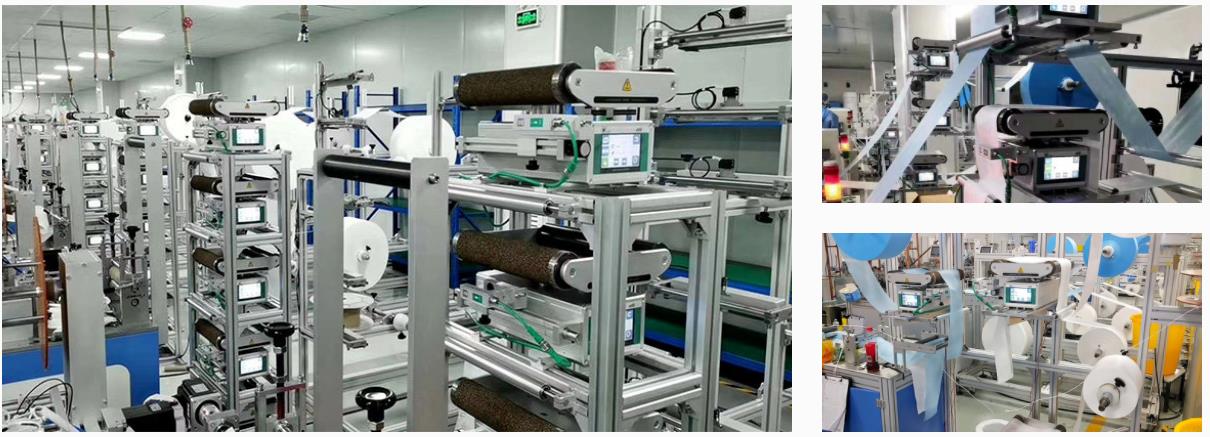
The active web guide system is composed of a sensor, an actuator, and a controller, which is a high-efficiency edge position control. The sensor can be any detector which can reliably pick up the edges of a web. The most common are pneumatic (nonporous webs), photoelectric (opaque webs), or paddies (thick webs). The web must be flat (free of curl) and stable (free of flutter) through the edge sensor. For this and other reasons, the sensor is often placed near a roller. If two sensors are used, the web could be guided to the front edge, back edge, or center.

The output of the sensor goes to a controller which outputs a movement command to the actuator. If the gain of the controller is too low, the response of the guide will be sluggish and slow to correct. If the gain of the controller is too high, the guide will be hot but overshoot, or may even be unstable. The actuator which moves the guide mechanism may be a stepper motor and ballscrew for smaller assemblies or a hydraulic cylinder for larger assembli`es. The actuator and framework must be stiff for responsive operation.
For more professional knowledge, please visit the page of web guide system articles.


commentaires